 Visual Paradigm Desktop |
  Visual Paradigm Online
The AI-Powered C4 Diagram Generator supports the four core levels of the C4 Model (Context, Container, Component, Deployment) plus essential supporting views to provide comprehensive architectural documentation.
Core C4 Diagrams
The Core C4 Diagrams are fundamental for documenting the static structure of your software system, detailing how it is broken down hierarchically.
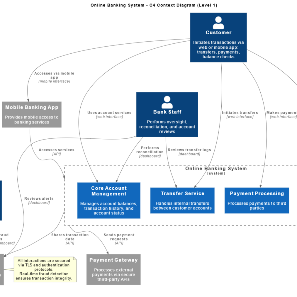
Context Diagram
Purpose: To place the software system being built in its environment. This is the highest-level view, designed for both technical and non-technical stakeholders.
What it shows: The system as a single “black box” in the centre, the users (people) who interact with it, and the other major software systems it depends on or interacts with.
Key Insight: What does the system do, and where does it fit into the bigger picture?
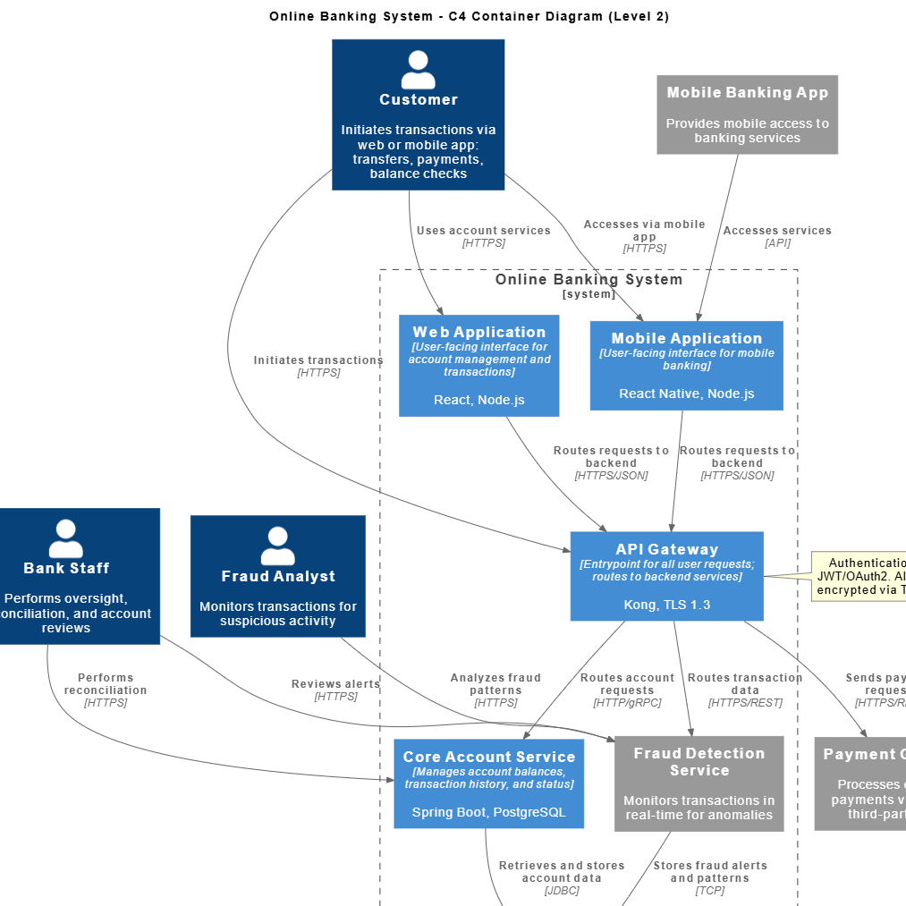
Container Diagram
Purpose: To show the high-level technical decisions about how the system will be implemented. This view is for architects and developers.
What it shows: The system’s ‘black box’ is opened to reveal the top-level Containers (applications, databases, file systems, single-page applications, mobile apps, etc.) that make up the system, their technology choices (e.g., Java API, PostgreSQL Database), and how they communicate (e.g., HTTPS, JDBC).
Key Insight: How is the overall system partitioned, and what technology hosts each major part?

Component Diagram
Purpose: To model the internal structure of a single Container. This view is for developers writing code within that container.
What it shows: The major Components (logical groupings of related code, such as classes or modules) within a specific container, their responsibilities, and how they interact with each other and with other containers.
Key Insight: What are the building blocks inside this application/service, and how do they collaborate to deliver the container’s functionality?
Architectural Link: This diagram is always scoped within a specific Container defined in the Container Diagram (Level 2), as components logically reside inside a container.
Supporting Diagrams
These diagrams provide specific views on interaction, flow, and portfolio management.
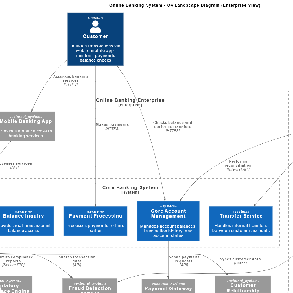
Landscape Diagram
Purpose: To provide an even higher-level overview than the Context Diagram, typically mapping out an entire portfolio of systems across an organization.
What it shows: All major software systems in an environment, their relationships, and often categorizations (e.g., internal vs. external, purchased vs. built).
Key Insight: What is the full scope of all systems managed by the team or organization?
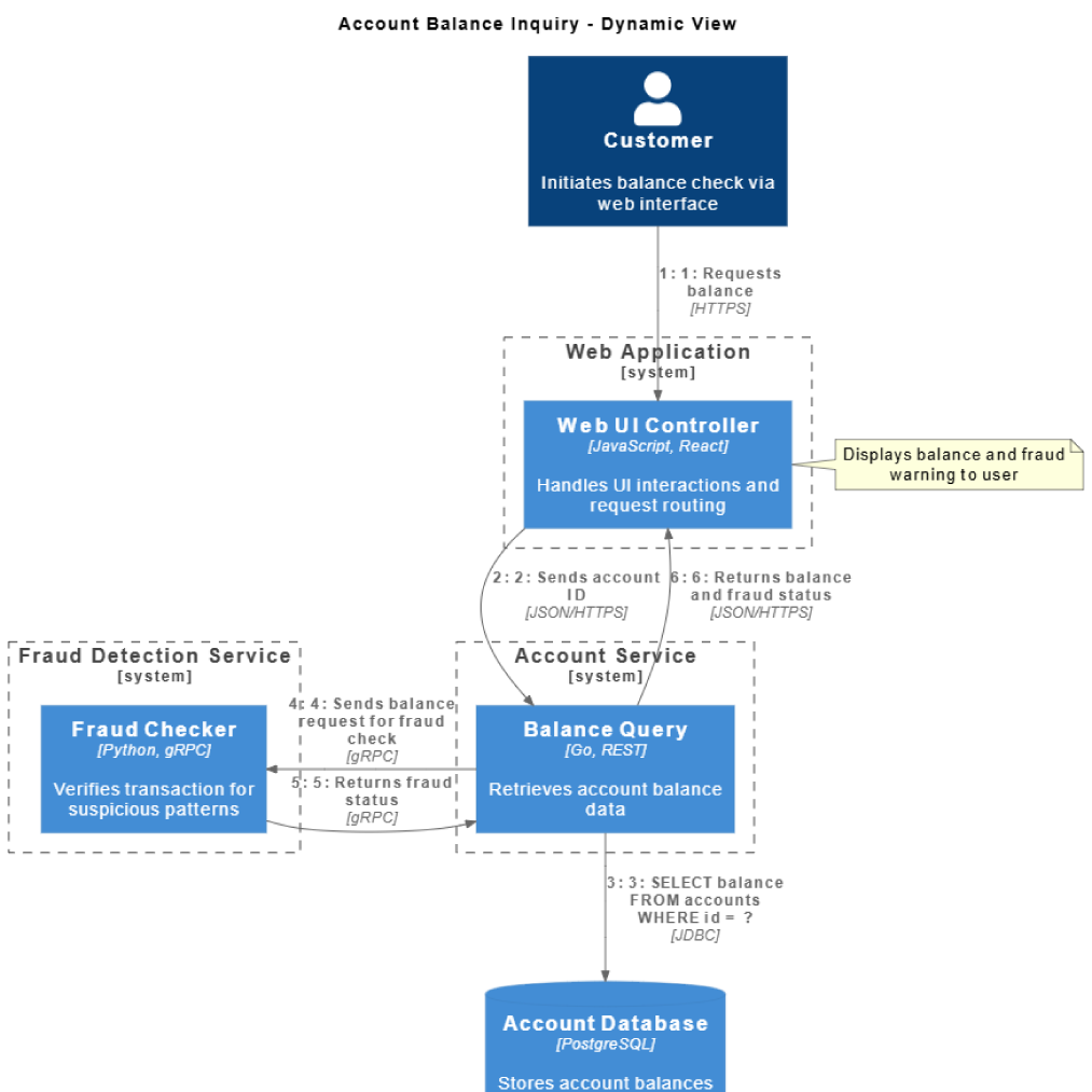
Dynamic Diagram
Purpose: To illustrate a specific collaboration or sequence of interactions between elements (containers or components) to fulfill a particular use case.
What it shows: A sequence of numbered calls between elements, demonstrating how a single feature or major transaction flows through the system.
Key Insight: How does the system achieve X use case step-by-step?
Architectural Link: This view describes the behavior and collaboration between elements (Containers and/or Components) that must first be structurally defined in the Container Diagram and Component Diagram.
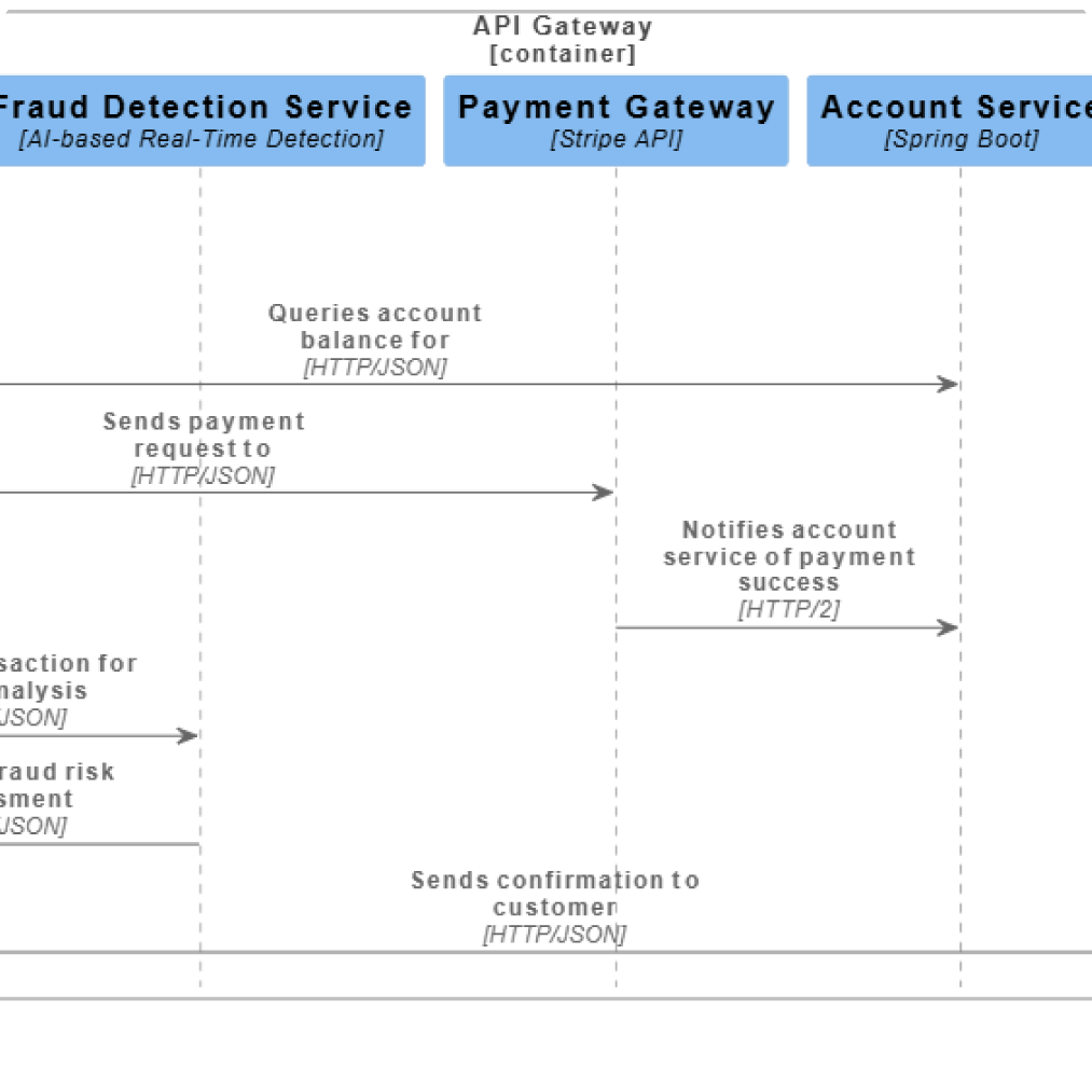
Sequence Diagram
Purpose: Similar to the Dynamic Diagram, but uses the standard UML notation for a sequence diagram (lifelines and vertical flow) to show the exact order of method calls and interactions over time.
What it shows: The precise ordering of messages passed between objects/components to execute a specific algorithm or business process.
Key Insight: What is the temporal flow and message passing order for this scenario?
Architectural Link: As a behavioral view, it relies entirely on the structural definition of its participants (Containers from Level 2 or Components from Level 3) to show a coherent message flow.
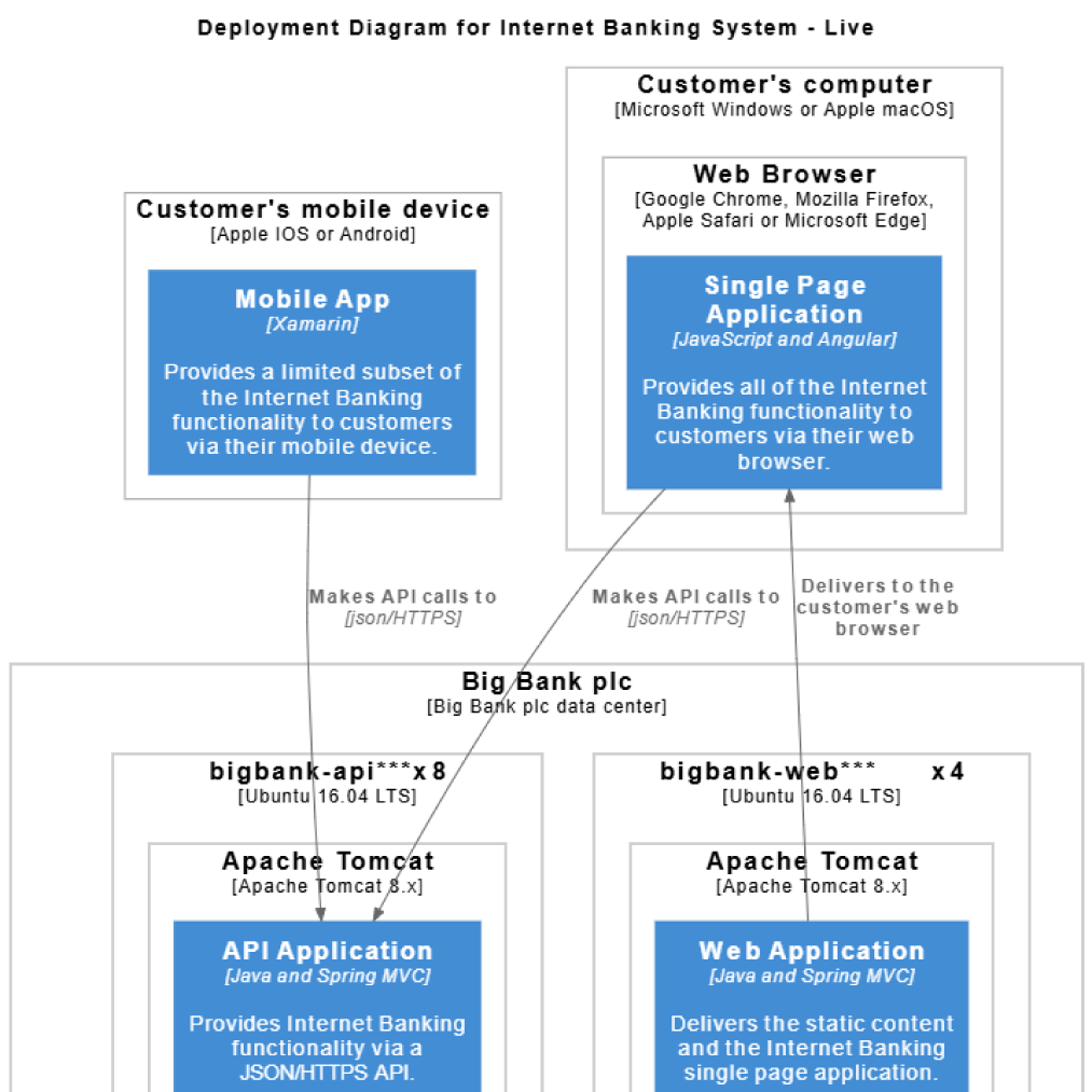
Deployment Diagram
Purpose: To show how the software containers (from Level 2) are mapped onto the physical infrastructure or cloud environments (e.g., servers, VMs, Kubernetes clusters).
What it shows: The environment topology, including physical nodes, operating systems, and the allocation of Containers to these nodes.
Key Insight: Where do the running containers and databases physically live, and what is the relationship between the hardware/cloud resources?
Instantly generate Context, Container, and Component diagrams from natural language descriptions.
