Visual Paradigm Desktop |
  Visual Paradigm Online
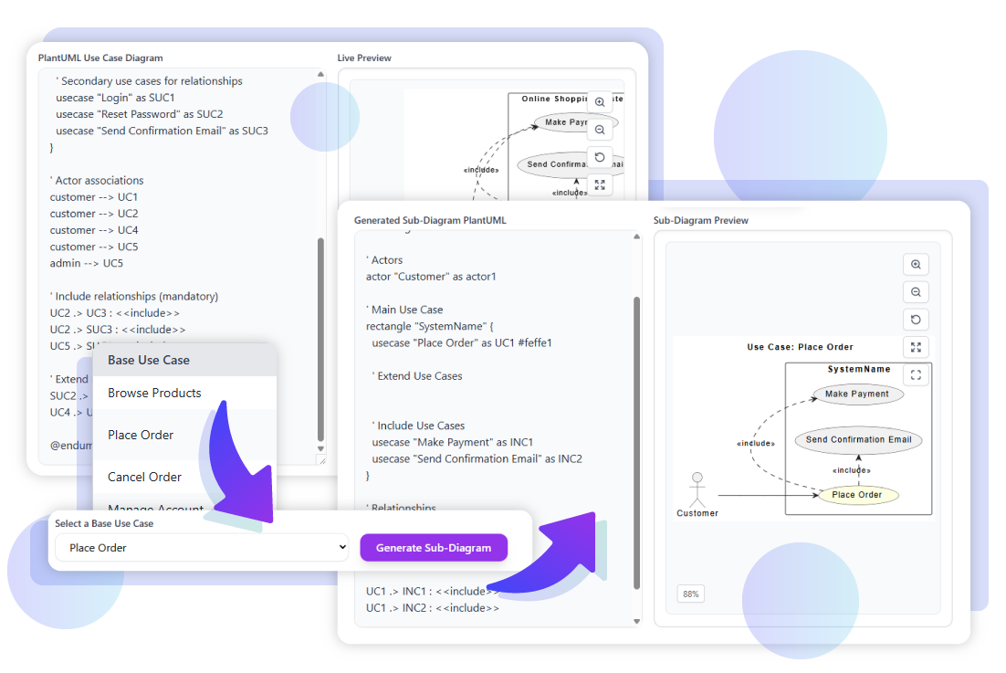
In an online shopping system, a customer places an order after browsing the product catalog. The order process involves making payment and receiving confirmation via email. This example will walk through how the Place Order use case and its related processes can be analyzed and visualized using the Extend and Include Use Case Analyzer.
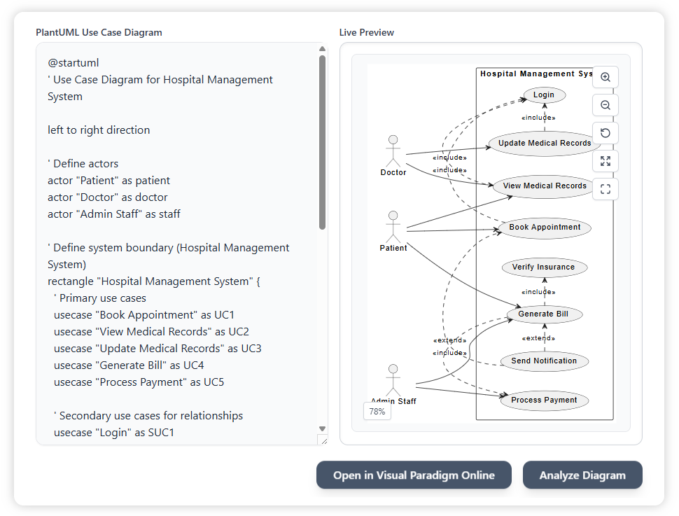
Start by entering the PlantUML code of the Online Shopping System into the text pane on the left. The diagram will automatically appear in the preview area on the right. Once ready, you can begin the analysis by pressing the Analyze Diagram button.
PlantUML Example:
@startuml
' Use Case Diagram for Online Shopping System

left to right direction

' Define actors
actor "Customer" as customer
actor "Admin" as admin

' Define system boundary (Online Shopping System)
rectangle "Online Shopping System" {
' Primary use cases
usecase "Browse Products" as UC1
usecase "Place Order" as UC2
usecase "Make Payment" as UC3
usecase "Cancel Order" as UC4
usecase "Manage Account" as UC5

' Secondary use cases for relationships
usecase "Login" as SUC1
usecase "Reset Password" as SUC2
usecase "Send Confirmation Email" as SUC3
}

' Actor associations
customer --> UC1
customer --> UC2
customer --> UC4
customer --> UC5
admin --> UC5

' Include relationships (mandatory)
UC2 .> UC3 : <<include>>
UC2 .> SUC3 : <<include>>
UC5 .> SUC1 : <<include>>

' Extend relationships (optional)
SUC2 .> SUC1 : <<extend>>
UC4 .> UC3 : <<extend>>

@enduml
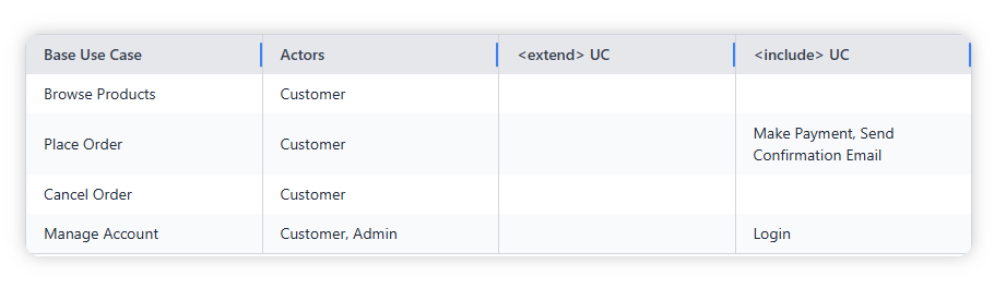
After analyzing, the system generates a summary table showing each base use case, its related actors, and the include or extend relationships. This helps you quickly understand how the use cases connect without manually tracing lines in the diagram.
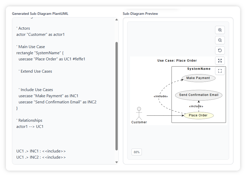
From the dropdown list, select Place Order as the base use case. This filters the diagram to only show the relevant actors and its include relationships, making the visualization much clearer.
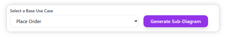
Click Generate Sub-Diagram to produce a simplified PlantUML diagram that highlights only the Place Order use case and its relationships. The diagram will be updated in the preview area, showing a clear view of the main flow.
Once the sub-diagram is generated, you can choose how to continue working with it: