 Visual Paradigm Desktop |
  Visual Paradigm Online
In software architecture, different UML diagrams serve different purposes. Two of the most commonly used are deployment diagrams and component diagrams. While they may look similar at first glance, each provides unique insights. Understanding when to use each helps you document systems more effectively and communicate the right details to your audience.
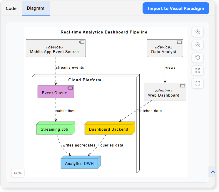
A deployment diagram shows the physical runtime environment of a system:
Use it when you want to answer questions like:
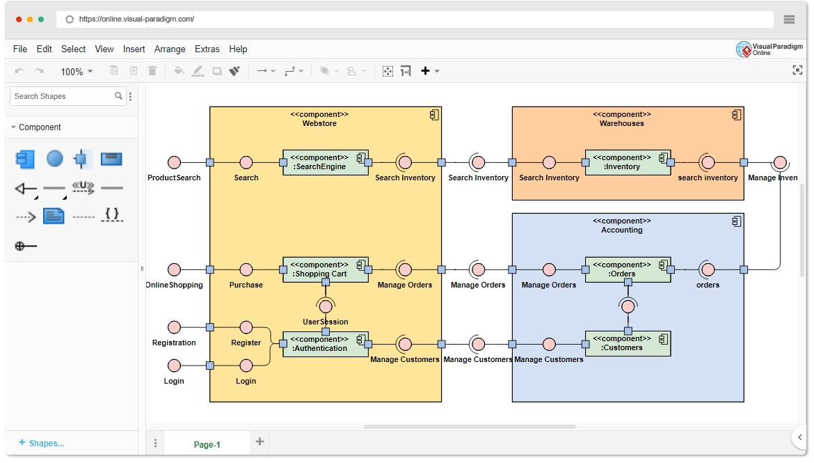
A component diagram focuses on the logical structure of the system’s software:
Use it when you want to answer questions like:
Focus: Physical infrastructure and runtime nodes
Shows: Servers, devices, containers, communication
Best for: Explaining infrastructure and runtime setup
Audience: DevOps engineers, system architects
Focus: Logical software structure
Shows: Components, libraries, interfaces
Best For: Explaining software architecture design
Audience: Developers, architects, designers
Best for infrastructure planning, DevOps workflows, cloud architecture, and explaining runtime environments.
Best for system design, module breakdown, API design, and showing internal structure of applications.
In many cases, both diagrams complement each other. A component diagram explains the logic, while a deployment diagram shows where those components live in the real world.
Deployment diagrams and component diagrams serve different but complementary purposes in UML modeling. Use component diagrams to capture the software’s internal structure, and deployment diagrams to show where that software runs in the real world. Together, they give a complete picture of your system architecture.
