 Visual Paradigm Desktop |
  Visual Paradigm Online
A UML Class Diagram serves as the foundational blueprint for a software system, providing a static, structural view of its classes, attributes, and the relationships between them. It’s the architectural drawing for your application.
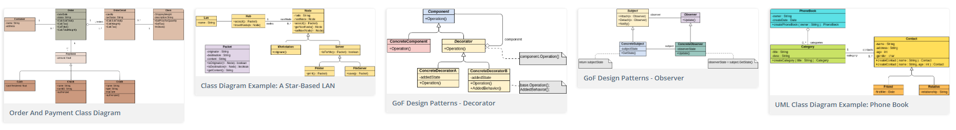
The central building blocks, represented by a rectangle divided into three sections: Class Name, Attributes (data), and Operations (methods).
Attributes define the data a class holds (e.g., name), while operations define the actions it can perform (e.g., login()).
Lines connecting classes that show how they are related. Key types include Association, Aggregation, Composition, and Inheritance.
Create a clear, high-level overview of a system’s structure to ensure the design is sound before development.
Map out key concepts within a business domain to better understand and validate requirements with stakeholders.
Provide a shared visual language for developers, business analysts, and managers to ensure everyone is on the same page.
Use a well-defined diagram as a blueprint to automatically generate code structures, improving consistency and saving time.
They use class diagrams as a map to understand the architecture of a system, making it easier to implement features, fix bugs, and refactor code efficiently.
By creating class diagrams, they can effectively model and communicate the business requirements and domain concepts to the development team.
Class diagrams help project managers estimate the complexity and scope of a project, which in turn aids in planning, resource allocation, and tracking progress.
